Why Steel Pipe Piles Hold Up in Marine and Waterfront Projects
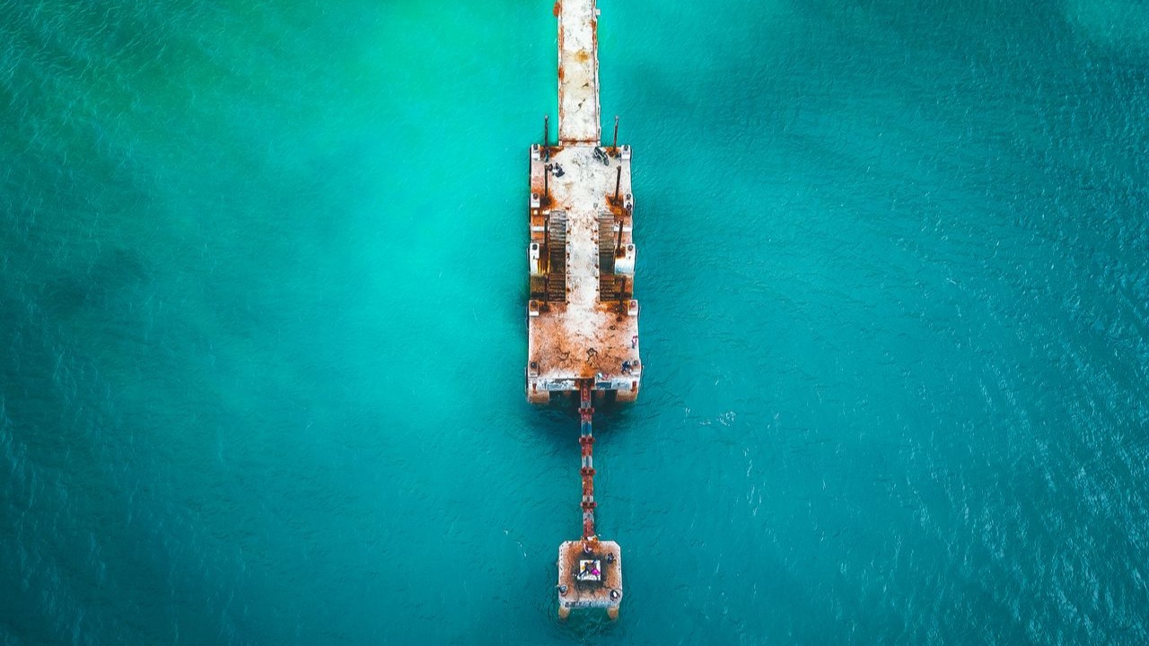
Marine foundations fail differently than land foundations. The structural loads are the same kind — compression, tension, lateral force, moment — but the environment that the pile lives in for its entire service life is categorically more aggressive than any terrestrial condition. Seawater, tidal cycling, splash zone exposure, biofouling, and sometimes ice loads create a degradation environment that eliminates many foundation options and puts steel pipe piles consistently at the top of the list for anyone who has to build something that floats, sits in water, or borders it.
Why the Marine Environment Is Different
Corrosion in seawater isn’t the same process as atmospheric corrosion. Seawater is a highly conductive electrolyte — the dissolved salts create the conditions for electrochemical corrosion to proceed at rates that would be surprising to anyone accustomed to thinking about steel in air. General corrosion rates for bare steel in seawater run roughly 0.1 to 0.3 mm per year in the fully submerged zone, with accelerated rates in the tidal and splash zones where alternating wet-dry cycles, oxygen availability, and wave turbulence compound the effect.
The splash zone — the region from just below mean low water to just above mean high water, including the wave action zone — is typically the most aggressive. Steel in this zone cycles between wet and dry, oxygen-rich and oxygen-depleted conditions, creating an environment where corrosion rates can be two to three times the fully submerged zone. This is the zone that drives the design of marine piling systems.
Biological fouling adds another dimension. Marine organisms attach to and grow on submerged steel, creating localized chemistry changes and crevice corrosion conditions under the fouling layer. For structural piles, biofouling is managed rather than prevented — it’s essentially unavoidable on any surface that remains submerged for more than a few months.
How Steel Pipe Piles Are Designed for Marine Service
The basic design approach for steel pipe pile in marine environments combines three elements: sacrificial thickness, protective coatings, and cathodic protection. Rarely is any single approach used alone; the combination is what produces service lives in the 50 to 100-year range that marine infrastructure projects require.
Sacrificial thickness is the simplest concept: specify a wall thickness greater than what the structural calculation requires, with the excess thickness intended to be consumed by corrosion over the design life. For a project with a 50-year design life and a splash zone corrosion rate of 0.3 mm per year, the sacrificial thickness allowance in that zone would be 15 mm — added to whatever the structural load calculation requires. This is a direct and verifiable approach, but it’s material-intensive and adds cost and weight.
Protective coatings in the splash zone reduce the base corrosion rate by creating a barrier between the steel and the environment. For marine piling, this typically means epoxy or coal tar epoxy systems applied over a blasted steel surface, sometimes topcoated with a UV-resistant coating for above-water portions. Coatings in the fully submerged zone are less effective because they’re difficult to inspect and repair; the submerged zone is usually handled with cathodic protection rather than relying on coating integrity.
Cathodic protection for the submerged zone uses either sacrificial anodes — zinc or aluminum alloy blocks attached to the pile — or impressed current systems where an external power supply maintains the pile at a potential that suppresses electrochemical corrosion. Impressed current systems require ongoing power and monitoring; sacrificial anode systems are passive but require periodic replacement as the anodes are consumed. For isolated piling systems like pier fenders or mooring dolphins, sacrificial anodes on a replacement schedule are standard. For larger, more complex port infrastructure, impressed current systems provide more controllable protection.
Lateral Load Behavior: Where Steel Pipe Piles Excel
Marine structures are almost always laterally loaded — by vessel berthing impact, mooring line pull, wave forces, current drag, and seismic loading for facilities in active zones. The lateral load capacity of a pile depends on its bending stiffness (EI), its diameter, and the passive soil resistance that develops as the pile deflects.
Steel pipe piles perform well in all three dimensions for marine lateral load applications. The high modulus of steel produces high bending stiffness relative to weight. The circular cross-section provides the same bending stiffness in any direction, which matters for a mooring dolphin or fender pile that may receive vessel impact from varying directions. Large-diameter pipes — 600mm to 1500mm or more for major port structures — develop significant passive soil resistance across a wide face area.
Prestressed concrete piles are common in sheltered marine environments but become impractical for structures subject to large lateral demands because concrete’s tensile capacity limits the bending moment the section can sustain. Steel pipe has no such limitation. Concrete-filled steel pipe piles — a steel pipe driven and then filled with concrete after installation — combine the corrosion resistance of steel exterior with the compression capacity of a concrete core, but the steel shell is still the element that carries bending.
Installation in Water
Driving steel pipe piles in water doesn’t fundamentally change the process — a crane barge or derrick barge provides the lifting and hammer support, and the pile is driven in the same way as on land. What changes is the logistics of maintaining pile alignment in current, managing hammer leads in tidal cycles, and coordinating with vessel traffic in active waterways.
For piles driven through water to a mudline where the soil bearing conditions exist, the unsupported length of the pile above the soil includes the water depth. This free-standing length above fixity in soil determines the effective pile length for lateral load analysis, and it’s often the governing design case for slender piles in deep-water marine applications. A pile that works fine structurally for the axial and lateral loads at the mudline may require a larger diameter or thicker wall when the full free-standing length above water surface is included in the lateral buckling analysis.